Please note: If you are looking for a Windows PC based system you should look here
Rugby MSF Atomic Clock
Circuit description
IC1 is the EM2S MSF pcb mounted chip produced by Galleon Systems and sold by Maplins for around 17 UKP. They also sell an antenna assembly, though any standard long wave ferrite rod antenna with a 2.2nF capacitor (C3) in parallel will do the same job. You must of course tune the circuit to 60 kHz which in an emergency can be done by simply sliding the coil up and down the ferrite rod until the red LED flashes. I used a separate coupling coil and an accurate signal generator set to 60 kHz to adjust the position of the coil.
IC2 is any 7404 hex inverter chip that can drive an LED. Tr1 is included because Galleon Systems show it on their diagram. Its base resistor can be connected to an output line of the user port and used to switch the receiver on or off remotely. I have omitted this connection because a printer port can be either input or output, not both. After all, these days few people have a user port.
D1 protects the circuit should the printer port be switched to output, which is of course its normal state. D3 is included because I drive the circuit from a 6V battery, as the 5V line from the user port is rather noisy and the printer port has no supply line. The diode drops the supply voltage to 5.3V. It also offers some protection against accidental reversal of voltage. (Try not to test this)! If you use a 5V supply you should replace this component with a link.
Apparently Maplins supply a data sheet for the radio chip. They failed to send it to me so all the component values were derived by experimentation. The circuit works extremely well for all that.
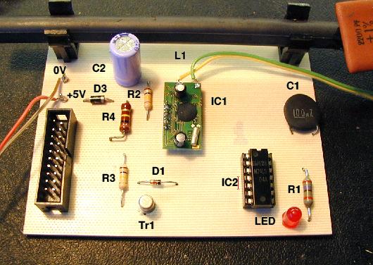
Below is the built circuit. You can get the draw file of the pcb negative via this link.
Building the thing
This is straightforward. The radio is mounted on four straight pins very similar to the audio connector inside a RiscPC. This gives the components on the underside of the radio pcb space to cool. The antenna pads are at the bottom. You can just make out the notch on the inverter chip and the key cutout of the dil connector. The red lead next to the black diode is the positive 6V supply line. The polarity of the diodes can just be made out, the cathodes point left. The component values can be found on the circuit diagram and their labels, ie R1, R2 .... have been superimposed on the photograph of the circuit.
I have prepared a drawfile explaining the construction of two leads. One is for use with the parallel printer port, the other for those that have a user port podule. Just click here.
The Program
Download the program from my shareware page. It is called !OvalTime. When you run it make sure that you click on the printer port button or the user port button, depending on what you are connected to. After powering the clock up it might take a few seconds to start. If the LED does not flash, turn the assembly around until it does. Ferrite rod antennas are directional. It takes a maximum of two or three minutes for the proper time to be displayed, depending on when you start intercepting the signal, so don't be surprised when the program displays complete rubbish in the first two minutes. It commonly imitates a time machine and displays a date several decades in the future. Pressing the info button will display a comprehensive help file for the program.
Computers and their monitors tend to interfere with reception. The further away the radio is from the computer, the better. Having said that, my setup is a foot away from the monitor and works fine, but the minute I switch on the PC or another RiscPC the receiver stops operating.
If you have any problems feel free to contact me. Good luck.
Useful links:
NPL Time Metrology National Physical Laboratory
Atomic Clocks Galleon
For those who don't know what an Acorn draw file is, use the gif below. It should be easy to scale it 0.1 inch dot separation.
The circuit worked in a fairly shaky fashion here in Northern Ireland, but it should give better results closer to the transmitter.
Whilst searching through some old files I came across the circuit below. The antenna is a standard long wave coil and the two connection labelled 'Twist for Feedback' are two wires which you twist to make a feedback capacitor. The more you twist the more feedback.