A Cassette Recorder Interface
- must have solenoid activated controls
- the push buttons - or their wiring - must be accessible
If these two conditions are met it is quite simple to design a small interface that enables you to control the tape deck via the computer. It is easy to learn if a deck is solenoid operated. If all the functions require only a very light touch and you can hear a metallic click when you press a button, you are in business. Programs can be written that turn the deck ON or OFF at a specific time or under certain conditions.
The cassette deck
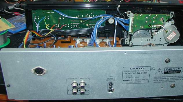
This is what my cassette deck looks like opened up from the back. The drive mechanism is on the right and part of the brown main pcb is visible. The green pcb in the top left hand half of the picture carries all the control switches of the cassette deck, each one mounted via four solder joints. I soldered a wire to the side of each switch that will go High when activated. The coloured ribbon cable I used is easily recognisable. All the original wiring is black, blue or white.
The top three wires lead to the Play, Rewind and Fast Forward buttons, the bottom three to the Record, Pause and Stop buttons. It was easy enough to identify the common ground and a wire was soldered to it as well. It is the green wire below the blue, second from the left. The other end of these connections lead to the 7 pin DIN plug visible on the left front of the picture. This wiring will not interfere with the function of the deck and is not noticeable once the cover has been fitted. It will however interfere with your warranty - you have been warned.
The circuit
The diagram above needs some explanation. There are six reed relays, though I show only two, the missing four are pure repetition. Each relay is shadowed by an LED to make writing a program easy on the tape deck. The cassette deck's 0V line is connected to the relays but not to the 0V line of the interface. This makes sure that the two systems are completely isolated from each other. There is a link to select connection to either port. Should you use the printer port you will also have to connect a 6V power supply. With the user port the 6V supply is redundant.
 The current sinking ULN 2803 takes care of the back emfs produced by
the relays. These should be small 5V reed relays that can switch at
least 0.5A. A suggested pcb layout is on the left. It can be printed
out with a laser or inkjet printer and transferred to a photo resist
board. Alternatively it should not be too difficult to design a Vero
board layout. RiscPC users
can download the original draw
file via this link.
The current sinking ULN 2803 takes care of the back emfs produced by
the relays. These should be small 5V reed relays that can switch at
least 0.5A. A suggested pcb layout is on the left. It can be printed
out with a laser or inkjet printer and transferred to a photo resist
board. Alternatively it should not be too difficult to design a Vero
board layout. RiscPC users
can download the original draw
file via this link.
 Finally
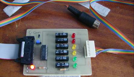
we come to the finished project. The blue link is set to the
user port option, hence no power supply is needed. The DIN plug fits
into the socket fitted to the back of the casette deck and the
multicore cable on the left connects to the user port. A program can
now be written that allows you to control most of the functions of the
cassette deck.
Finally
we come to the finished project. The blue link is set to the
user port option, hence no power supply is needed. The DIN plug fits
into the socket fitted to the back of the casette deck and the
multicore cable on the left connects to the user port. A program can
now be written that allows you to control most of the functions of the
cassette deck.
I have written a very simple multi-tasking demonstration called !TapeCon It allows you to use all the controls but has no fancy timing routines. If you decide to build this project, you must obviously have a suitable tape deck that allows access to the switches. Come to think of it, the principle would be the same for a video recorder or indeed any push button operated electronic equipment that uses solenoid control.
If you need any help, drop me an email and I'll try my best.