A radio operated four socket mains
controller
This project uses UK
plugs and sockets - if you live elsewhere on this large planet, your
equipment may look different.This little project relies for most of the hardware on a gadget bought in a supermarket. The unit cost 15 pounds and consists of a small remote control which contains the transmitter and four receivers, which plug into any available socket and into which in turn you can plug any mains driven equipment that uses up to 13 amps. The receivers can be programmed individually or in groups and can then be turned on and off with the remote control's buttons. It is a nice unit in its own right and very useful for sockets in awkward places - like most power outlets in my well equipped playpen.
It occurred to me that this might be an ideal way to control mains equipment with a computer. No dangerous voltages, no cables all over the place and a nice, elegant addition to my favourite hobby - and so it proved to be. This could also be a very useful help for a handicapped person who can operate a computer, but can't reach mains equipment, because the receiver unit can be in any socket in the same or adjacent room, depending on radio propagation.
The only brain work required involves tracing the layout of the transmitter's circuit board. The switch connections form a matrix. Four wires for the four receivers and two to select either on or off. It turned out that the back of the PCB had convenient solder joints for all connections. In fact, if the extra wires are carefully positioned the unit remains totally functional and can be used either from the computer or by hand.
Here is how to proceed.
Remove the battery and carefully open the case. Prise it open with a small screwdriver applying pressure from all sides starting at the seam. There are no screws, the two halves of the shell are held together by four circular wedges. To re-assemble the unit you simply line up the two halves and squeeze them gently together.
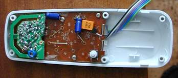
A word of warning. I have destroyed at least one of these units with static electricity. I would strongly advise to use an earth strap before you touch the pcb.
The back of the PCB is now exposed. Undo four small screws and remove the pcb from the case. The switch side is now accessible and shown in the photograph with the six new wires already attached. I have marked each individual solder point with a white circle. The round silvery discs are steel spring-discs which snap closed when pressed and hence close the circuit. They are held in place, believe it or not - by bits of scotch tape. You have to remove some of this in order to get at the solder joints.
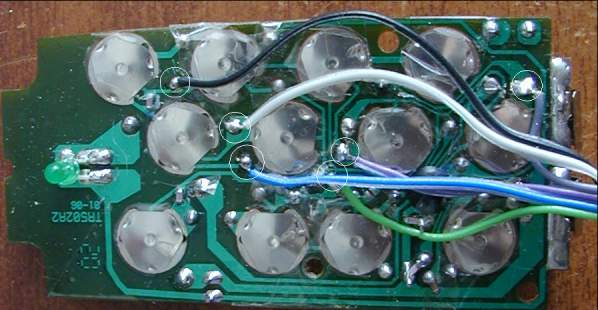
The black and the white wires are connected to the on/off signal (1 and 2 on the circuit diagram), the other four are for the four sockets. If you connect any of these four wires to the white, the corresponding On signal is sent, connect them to the black and the Off signal is transmitted.
Once the six wires have been attached put the pcb back into its case, jiggle it about a bit to make sure that none of the wires jam a switch and fasten the pcb with the four small screws. I removed some plastic from the side of the casing to make room for the wires. Close the unit, taking care that the little switch near the battery does not jam and attach the connector to the ends of the wires.
Designing the interface was straight forward. The two systems are electrically completely separated by the use of four reed relays and one small changeover relay. The five relay coils are connected to five output ports of the Velleman interface board.

A suggested pcb layout is shown below. If you can't get the (rather ancient) reed relays I used, you will obviously have to redesign the board to suit your own needs.

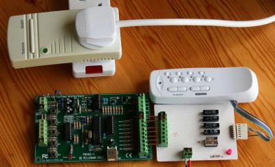
Below
is the complete
system. Any buttons activated via the Velleman board are transmitted to
the unit plugged into the socket. This in turn switches whatever it is
connected to on or off.
The
program
The logic of this very simple effort is best explained with the help of the truth table below.
 In
my
set-up, the unit is connected to ports 3 to 7 of the Velleman
K8055 interface board. Port 1 and 2 are not used, hence they stay 0 at
all times. Port 3 is responsible for either On or Off, the
other ports send the signals to their respective receiver unit.
In
my
set-up, the unit is connected to ports 3 to 7 of the Velleman
K8055 interface board. Port 1 and 2 are not used, hence they stay 0 at
all times. Port 3 is responsible for either On or Off, the
other ports send the signals to their respective receiver unit.
Example:
In order to switch the receiver connected to Port 3 On, we send the pattern 0001100 to the output port, were the two rightmost zeroes represent ports 1 and 2, which are not used but must have their place in the binary pattern.
To
turn Port 3 Off, we send the
pattern 0001000, and so on.
In the simple program below I have assigned the keys 1-Q, 2-W, 3-E, and 4-R to the four receiver units. The numbers turn the units on, the letters turn them off again. It is necessary to send the pattern as a short pulse, half a second or so is sufficient. If you leave any output high for a long time, the unit will quickly have its battery drained, because the signal is sent all the time.
As usual, here is a link to the BBC BASIC file Mains Controller
The program is kept very simple. Lines 260 to 390 interrogate the keyboard and send the required pattern to PROCsend as soon as a legal key is pressed.
PROCsend
outputs this pattern to the output port of the Velleman board for half
a second, and then turns all ports off.
 10 REM Mains controller
 20 REM Version 1.0
 30 REM Switch up to four mains units
 35 REM Jochen Lueg
 40 REM Limavady, February 2011
 50
 60
 70 PROCinit
 80
 90
 100 T%=50
 110 SYS USB_OpenDevice%, 1: REM I'm using a Velleman board with address 01
 120 SYS USB_ClearAllDigital%
 130
 140 REM Unit 1 On 1 Unit 1 Off Q
 150 REM Unit 2 On 2 Unit 2 Off W
 160 REM Unit 3 On 3 Unit 3 Off E
 170 REM Unit 4 On 4 Unit 4 Off R
 180
 190 PRINT" Unit 1 On 1 Unit 1 Off Q "
 200 PRINT" Unit 2 On 2 Unit 2 Off W "
 210 PRINT" Unit 3 On 3 Unit 3 Off E "
 220 PRINT" Unit 4 On 4 Unit 4 Off R "
 230 PRINT
 240 PRINT "Exit program S"
 250

 260 REPEAT
 270 IF INKEY(-49) PROCsend(%00001100)
 280 IF INKEY(-17) PROCsend(%00001000)
 290
 300 IF INKEY(-50) PROCsend(%00010100)
 310 IF INKEY(-34) PROCsend(%00010000)
 320
 330 IF INKEY(-18) PROCsend(%00100100)
 340 IF INKEY(-35) PROCsend(%00100000)
 350
 360 IF INKEY(-19) PROCsend(%01000100)
 370 IF INKEY(-52) PROCsend(%01000000)
 380
 390 UNTIL INKEY(-82)
 400
 410 SYS USB_ClearAllDigital%
 420 END
 430
 440
 450 DEFPROCsend(Ports%)
 460 SYS USB_WriteAllDigital%,Ports%
 470 TIME=0
 480 REPEAT UNTIL TIME>T%
 490 SYS USB_ClearAllDigital%
 500 ENDPROC
 510
 520
 530 DEFPROCinit
 540 REM Typing errors in routine name do not generate an error message - they just hang up the program.
 550 SYS"LoadLibrary","K8055D.dll" TO USB_Board%
 560 SYS"GetProcAddress",USB_Board%,"OpenDevice" TO USB_OpenDevice%
 570 SYS"GetProcAddress",USB_Board%,"ReadAnalogueChannel",1 TO USB_ReadAnalogue%
 580 SYS"GetProcAddress",USB_Board%,"SetAllDigital" TO USB_SetAllDigital%
 590 SYS"GetProcAddress",USB_Board%,"CloseDevice" TO USB_CloseDevice%
 600 SYS"GetProcAddress",USB_Board%,"ClearAllDigital" TO USB_ClearAllDigital%
 610 SYS"GetProcAddress",USB_Board%,"ClearDigitalChannel" TO USB_ClearDigitalChannel%
 620 SYS"GetProcAddress",USB_Board%,"SetDigitalChannel" TO USB_SetDigitalChannel%
 630 SYS"GetProcAddress",USB_Board%,"WriteAllDigital" TO USB_WriteAllDigital%
 640 ENDPROC
 650
 660