Please note: If you are looking for a Windows PC based system you should look here
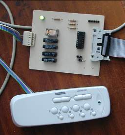
A radio operated four socket mains controller
It consists of a small remote control which contains the transmitter and four receivers, which plug into any available socket and into which in turn you can plug any mains driven equipment that uses up to 13 amps. The receivers can be programmed individually or in groups and can then be controlled with the remote control buttons - four on, four off, all on, all off. It is a nice unit in its own right and very useful for sockets in awkward places - like most power outlets in my well equipped playpen.
It occurred to me that this might be an ideal way to control mains equipment with a computer. No dangerous voltages, no cables all over the place and a nice and elegant addition to my favourite hobby - and so it proved to be. This could also be a very useful help for a handicapped person who can operate a computer, but not mains equipment.
The only brain work required involved tracing the layout of the transmitter's circuit board. The switch connections form a matrix. Four wires for the four receivers and two for on/off. It turned out that the back of the PCB had convenient solder joints for all connections. In fact, if the extra wires are carefully positioned the unit remains totally functional and can be used either from the computer or by hand.
Here is how to proceed.
Remove the battery and carefully open the case. Prise it open with a small screwdriver applying pressure from all sides starting at the seam. There are no screws, the two halves of the shell are held together by four circular wedges. To re-assemble the unit you simply line up the two halves and squeeze them gently together.
A word of warning. I have destroyed at least one of these units with static electricity. I would strongly advise to use an earth strap before you you touch the pcb.
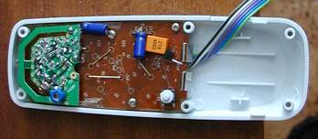
The back of the PCB is now exposed. Undo four small screws and remove the pcb from the case. The switch side is now accessible and shown in the photograph with the six new wires already attached. I have marked each individual solder point with a white circle. The round silvery discs are steel spring-discs which snap closed when pressed and hence close the circuit. They are held in place, believe it or not - by bits of scotch tape. You have to remove some of this in order to get at the solder joints.
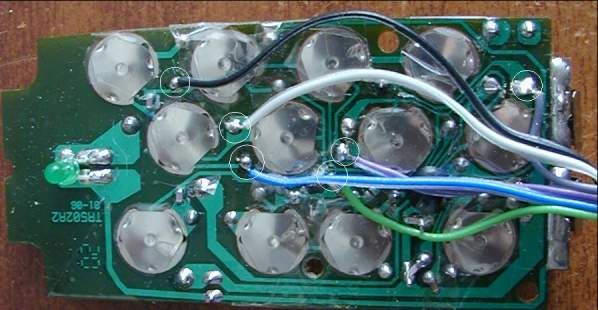
The black and the white wires are connected to the on/off signal, the other four are for the four sockets. Socket 4 is grey, socket 3 is violet, socket 2 is green and socket 1 is blue. If you connect any of these four wires to the white, the corrresponding On signal is sent, conect them to the black and the Off signal is transmitted.
Once the six wires have been attached put the pcb back into its case, jiggle it about a bit to make sure that none of the wires jam a switch and fasten the pcb with the four small screws. I removed some plastic from the side of the casing to make room for the wires. Close the unit, taking care that the little switch near the battery does not jam and attach the connector to the ends of the wires.
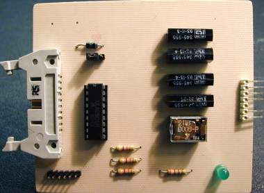
Designing the interface was straight forward. The two systems are electrically completely separated by the use of four reed relays and one small changeover relay. All are driven by a ULN 2801 type darlington driver which already contains protecting diodes. As only five lines are used, I have provided a switch connector wired to three pull up resistors. This way one can write programs that interact with the outside world, turning mains equipment on or off as required. Here is the circuit diagram:
The pcb layout is shown below and
here is a link to the draw file,
should you want to print it out and you are wise enough to own a
RiscPC.