|
The motion sensors
Below is the entire
apparatus. A and B are two old and
now dysfunctional hard drives. Removing
the discs gives access to the pickup arm which in turn is driven by
what is known as a 'voice coil'. This coil is suspended between two
very powerful magnets. Energising the coil will react with the magnetic
field and drive the pickup across the disc surface. Like all such
arrangements it can be used in reverse, ie. if you move the pickup arm,
a current is produced in the voice coil, which when amplified, can be
interpreted by a computer program.
 C is a very heavy weight made from roofing lead. This is suspended from
the ceiling with a length of picture wire. D is an arrangement of
activators attached to the weight. They are in close contact with the
drive's pickup arm, which is pressed against the activators by the
springy cable which connects the pickup assembly to the rest of the
hard drive. One sensor will detect horizontal - the other lateral
movement. When the ground moves, the suspended lead weight tends to
remain stationary and so the two moving pickup arms will push against
the activators, thereby generating a small current in the voice coils.
E and F are two lead weights
that keep the apparatus steady. G is a switch arrangement allowing
selection between the two coils. Either A or B, or A and B in series.
The latter is the most effective configuration.
As far as I know no-one has
ever used hard drives for this purpose and I like to think that the
'Lueg earth quake detector' is an original invention.
The arrangement is very
effective because the two voice
coils were originally designed to drive the pickup arms at high speed,
which means that they have a very low resistance. This in turn means
that they do not suffer from electro magnetic interference. I found no
need to filter out mains hum even though four computers and a monitor
were operating just a metre away.
|

 C is a very heavy weight made from roofing lead. This is suspended from
the ceiling with a length of picture wire. D is an arrangement of
activators attached to the weight. They are in close contact with the
drive's pickup arm, which is pressed against the activators by the
springy cable which connects the pickup assembly to the rest of the
hard drive. One sensor will detect horizontal - the other lateral
movement. When the ground moves, the suspended lead weight tends to
remain stationary and so the two moving pickup arms will push against
the activators, thereby generating a small current in the voice coils.


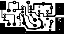
 The complete electronic setup
is on the right. A is
a ready built A to D converter module made by Unilab, together with B,
a small cable adaptor. The converter board uses a ZN449 8-bit converter
and is quite versatile - my life wouldn't be the same without it. Any
other eight bit A/D converter will do just as well of course, as long
as it is compatible with your computer. C is
the amplifier described above.
